This is part 8 of my Building a Processor series, where I try to build a processor on an FPGA board. This post is about getting the UART peripheral to work so that I can communicate directly between the board and my computer.
Previous: further optimizing the debouncer.
In my previous post, I brought up the idea of building a Bitcoin miner out of my fpga board. The algorithms for it are pretty simple: iterate over a counter, and take the double-sha256 hash of that counter plus some other material, and output once the resulting hash is small enough.
The tricky part is that this isn’t a static problem, and you have to be constantly getting work from the network in order for your hash results to be relevant. I suppose it’d be possible to use the ethernet port on the Nexys3 and have this functionality be self-contained on the board, but I think it would be much easier to handle as much as possible on the computer, and only offload the mass hashing to the fpga. This means, though, that I need some form of communication between my computer and the fpga, and I’m not sure that the programming cable can be used for that.
UART transmitter
So, to use the UART interface on the microusb port, we communicate through the FTDI FT232R chip. This chip is connected by just two lines to the FPGA, just a TX and an RX line. While the low pin-count certainly makes it seem simple, I’ve never seen a communication interface that only uses a single wire (per direction) to communicate. Unfortunately, the Nexys 3 reference manual, while very helpful for most of the other board functionality, seems to mostly assume that you know how serial ports work or that you can figure it out. The FT232R datasheet is unhelpful in a different way, in that it gives you way too much information, and using it would require cross-checking the datasheet against the Nexys 3 schematics to see how all the different lines are hooked up.
Fortunately, Digilent released the source code to their demo project that comes preloaded on the device, and unbeknownst to me when I first ran it, this program actually transmits over the serial port. Between this and the Wikipedia page for RS232, I was able to get the transmission working: it turns out that the protocol is extremely simple and some combination of the FT232R and the controller on the pc side makes the channel very resilient. Essentially, you pick a supported baud rate, and output signals onto the TX line at that rate. You can start any symbol at any time, but each bit of the symbol should be held for close to the period determined by the baud rate. I’m not sure exactly what the FT232R does (maybe it just transmits the bit changes?), but by programming the baud rate into the receiving end, plus the redundancy provided by the start+stop bits, it ends up “just working”.
The other side of the communication equation is that you have to set up something on your computer to actually receive the data. There are some options that seem highly recommended, but I found this project called pyserial, which you can install with just “easy_install pyserial”, which makes it easy to read+write to the serial port from Python. You can see the initial version of all of this here.
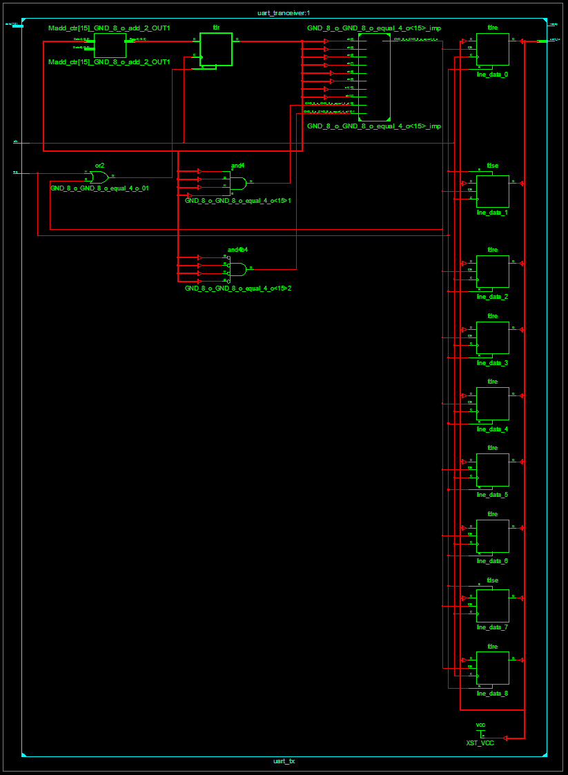
This version has size 111/126/49 (reporting the same three numbers as in this post: Slice Registers, Slice LUTs, and Number of occupied Slices). The RTL for the transmitter seems quite inelegant (click to enlarge):

So I decided to optimize it. Currently, the circuit works by creating a 10-bit message (8-bit data plus start and stop bits), and increasing a counter to iterate over the bits. It turns out that “array lookup” in a circuit is not very efficient, at least not at this scale, so what I’m going to do is instead use a 10-bit shift register, always send the lowest bit, and shift in a 1 bit (the “no message” signal) every time I send out a bit. You can see the improved schematic here:
The schematic is now much more reasonable, consisting primarily of a shift register and a small amount of control logic; you can also notice that the synthesizer determined that line_data[9] is always a binary ‘1’ and optimized it away, which I was happy to see. Though again, even though I much prefer the new schematic, the area parameters haven’t changed: they’re now 114/130/47. Maybe I should stop trying to prematurely-optimize the components, though it is satisfying to clean it up.
UART receiver
Once I knew what the protocol is, the receiver wasn’t too much work. The basic idea is that the receiver waits for the first low signal, as the sign that a byte is coming. If the number of clock cycles per bit is C, the receiver will then sample the receive line at 1.5C, 2.5C, 3.5C, 4.5C, 5.5C, 6.5C, 7.5C, and 8.5C, which should be the middles of the data bits. The protocol actually seems pretty elegant in how easy it is to implement and how robust it ends up being to clock frequency differences, since the clocks are resynchronized with every byte that’s transferred.
One mistake I made was that it’s important to wait until time 9.5C before becoming ready to sense a new start bit; at first I immediately went back into “look-for-start-bit” mode after seeing the last bit at 8.5C, so whenever I sent a symbol with a 0 MSB (like all ascii characters), the receiver would incorrectly read an extra “0xff” byte from the line. You can see the code here.
Buffering
So at this point I have bidirectional communication working, but the interface is limited to a single byte at a time. So next, I’m going to add a fixed-length multi-byte interface on top of this; I’m going to say that the protocol has two hard-coded parameters, T and R, where all messages going out of the FPGA are T bytes long, and all messages in are R bytes. If we try to transfer while a multi-byte transfer is still in progress, and we’ll keep a buffer of the most recent R-byte message received, but if we fail to pull it out before the next one comes in we’ll replace it. To keep things simple, let’s actually say that the messages are 2^T and 2^R bytes long.
I wrote the multibyte transmitter by hand; I think another good option is to have written it using the builtin FIFO generator IP Core, but I wanted to try it for myself, and plus I have a growing distaste for the IP Core system due to how godawful slow it is. Anyway, you can see the commit here.
The receiver was a little trickier since I had to frame it as a large shift register again; maybe I should have done that with the multibyte-transmitter as well, but the synthesizer wasn’t smart enough to tell that assigning to a buffer byte-by-byte would never try to assign to the same bit at once. You can see the commit here.
Writing the driver for this is interesting, since restarting the driver might leave the fpga with a partial message; how do you efficiently determine that, and resynchronize with the board? The simplest solution is to send one byte at a time until the board responds, but that involves N/2 timeouts. I haven’t implemented it, but I’m pretty sure you can do better than this by binary searching on the number of bytes that you have to send from your initial position. In practice, I’ll typically restart both the PC console script and the FPGA board at the same time to make sure they start synchronized.
That’s it for this post; now that I have the FPGA-pc communication, I’m going to start building a sha256 circuit.

7 responses to “Building a Processor, Part 8: UART Communication”
Hello Kevin
Just curious about what schematic viewer you are using…Synopsys ?
Thx
JCLL
LikeLike
Hi Jean-Christophe, this is just the viewer that’s built into Xilinx’s ISE.
LikeLike
Hi Kevin,
I really dont understand the how the transmission works, did you use the uart usb or the serial port in the end? Im trying to simulate the same thing but Im not really sure whats going on?
Thanks,
J.
LikeLike
Hi James, let me know if I’m misunderstanding your question — on my board, the UART is hooked up to an FT232R UART-to-USB bridge. I usually use the term “serial port” interchangeably with “UART” since I don’t think I’ve ever used actual RS232 signalling levels.
LikeLike
Oh okay I see, I was just getting a bit confused. So I send data from the host computer via FTDI chip to the tx line and then onto the FPGA?
J.
LikeLike
Yeah, though I guess it can depend on the dev board. You shouldn’t have to worry about the precise details of how it’s implemented, as long as you figure out which FPGA pin is the TX and which one is the RX (should be in the dev board manual/schematics) and how to connect to it on your PC (something like /dev/ttyUSB0 on Linux, something like COM0 on Windows I think).
LikeLike
Okay, Im using the Nexys 3 so I think I have to use the MCU-RX/ MCU-TX line so I will download the VCP drivers and have a play around with the demo. But Im still not sure how Im meant to get some sort of simulation that shows the correct information is being sent if you get me. Like I want to see my bit combination being sent from the FTDI chip to the FPGA on ISim if that’s possible?
J.
LikeLike