I’m late in writing this post since Hackweek was a few weeks ago now, but better late than never I suppose.
As I mentioned in my previous hackweek post my goal was to use my new 3D-printer to build some parts for a simple robot.
Unfortunately, getting the 3d-printer working took four out of the five days of Hackweek, so there wasn’t much time to get the robot going. I was able to multi-task somewhat, since calibrating the printer involved many periods of waiting for test prints, so I was able to build a simple robot, though the “3d-printed” aspects were minimal. Getting a basic working is surprisingly simple: get some simple DC motors, and apply a voltage across the terminals and they go! These particular motors are small enough that they can be driven with a single LiPoly battery.
Using alligator clips to connect the battery and the motor is all fun and good, but eventually I wanted to control the motors from my ATmega. I used a single L298N motor driver to drive two H-bridges, one per motor, which was surprisingly straightforward (I just built the “typical application” circuit from the datasheet). For input, I used this joystick with the associated breakout board, and “mounted it” on a small breadboard as a simple control:

I used one of my ATmega328 Arduino-like boards to read the analog readings from the joystick (which is just two potentiometers), and use those readings to implement a differential drive control on for the robot. Here’s another pic of the on-robot electronics:

So electronically, this set up is extremely simple, and not very innovative; once I had all the parts, it probably only took a few hours to have the wheels turning. Sidenote: maybe I’ll write another post about this, but I’m learning that surprisingly, part-selection is where I spend most of the project’s design time, since picking the parts involves knowing how they will all fit together, and verifying whether a part will work usually involves a relatively-complete idea of the design as a whole.
Base plate
It was definitely educational to get the motors turning, especially as controlled by a joystick, but the hard part of the project for me was building a chassis for all the parts. There very first “chassis” I used consisted of just the three main parts (gearbox, breadboard, arduino) taped together, with no rear castor, so the breadboard was dragging along the floor. I decided I wanted a baseplate to mount the gearbox + castor on, so I came up with this T-shape:

Sorry this is the only picture I have; imagine that it’s filled in and about 0.5cm tall.
What are those three squares, you say? Well, my idea was to mount the gearbox using self-tapping screws, screwing them directly into the baseplate. I’ve been printing most of my parts at low “infill density” — ie while the part looks solid, the inside is only 20% full, to save on materials and printing time — thus I was worried about whether there was enough material to actually screw into. Ideally I’d be able to print those three screw-areas at 100% fill density, and while the 3d-printer is certainly capable of doing that, Slic3r, my slicing program (the program that takes 3d models and produces a series of line segments) didn’t seem capable of it.
So instead, I decided to try creating these small square holes, and to create square “screw plugs” that would fit into them, with small caps on the bottom so that the base plate could rest on them (sorry for the lack of a picture).
This design worked, though there were enough issues that I’m not tempted to do it again. Assembly became pretty complicated, since there was now an additional piece to hold in place while placing the screw. The plugs added a bunch of play to the base plate, both in the XY plane, but also in the Z axis (I think this could have been avoided by making the plugs shorter than the hole). In the future I think I’m going to try just using untapped holes, and use a nut+washer combination on the other side; I think this will be more reliable and not require separate parts.
Breadboard holder
The base plate let me attach the gearbox and the castor, and with some tape I was able to have a barely-structural robot. It quickly became clear, though, that I needed something to hold the pcb above the gearbox, since it kept on sliding around and would eventually hit the wheels and the whole contraption would fall apart. Here’s the design I came up with; these are the three iterations of it, from earliest on the left to final on the right:
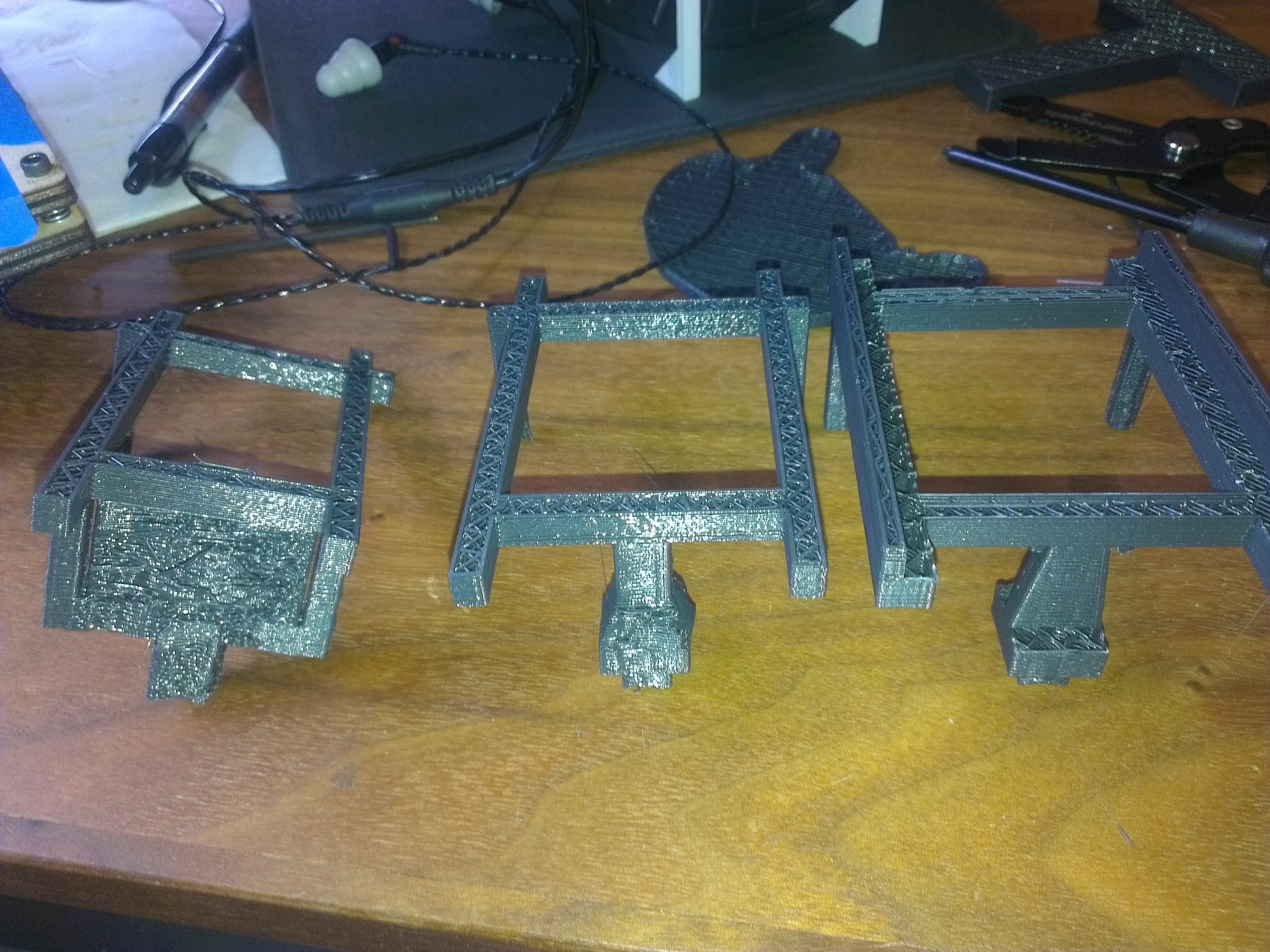
The first design had several issues, the worst of which was that it was the wrong size, and secondly that it required a fair amount of support material. The second iteration was the first that worked, but I realized that I wanted guard rails to hold the breadboard in place, which is the main change between v2 and v3. You can see how it mounted on the baseplate:

It had a fair amount of XY stability, but if I were to go back to it, I’d add a small piece on the bottom that would keep it attached to the baseplate, since right now it comes right off when pulled upwards.
Here’s a video of it driving; this is before I created the breadboard holder, and you can tell it lacks structural integrity (though one could say it makes it up in spunk):
Overall, even though the 3d-printing aspect didn’t turn out how I wanted, I found the experience of building a robot from scratch to be very rewarding, so stay tuned since there will be more robotics-related projects coming up 🙂
