For the past couple weeks I’ve been working on a new project: implementing a brushless motor (bldc) driver, with the distant goal of building a quadcopter from scratch. Sidenote — I’m still narrowing in on what I consider to be doing something “from scratch”. BLDC drivers (apparently called “ESCs” in the RC world) seem to be easy to buy, but I wanted to build them myself. I’m having the pcbs made by OSH Park, but the pcb fabrication isn’t something that I feel like I need to do myself; same goes for the motor construction. And I think this can change over time; I bought a cheap quadcopter frame for testing, but I plan to eventually build my own frame.
Anyway, there are a couple things that I found challenging in designing the driver:
- Learning the theory of the control — it’s not as simple as “simply apply a voltage and it goes”, like the brushed DC motors I used for my simple robot. There are several good resources out there on this, though; somewhat surprisingly, though I guess it makes sense once you think about it, the best references are by different IC manufacturers who try to help you build your BLDC driver using their products. Anyway, here were the ones I found most helpful:
- Microchip AN857: Brushless DC Motor Control Made Easy
- Atmel AVR444: Sensorless control of 3-phase brushless DC motors [using the ATmega48]
- Silicon Labs AN208: Sensorless Brushless DC Motor Reference Design
- Parts of the control algorithm — specifically, the back-emf sensing required for sensorless control — only work at high speeds, which makes the system hard to debug.
- It takes a surprising amount of power to lift even moderate weights using propellers. The motors I bought are 300W — by comparison, the motors on my previous robot were sub-1W. There are two things that this means: a separate supply voltage (12V), and much higher currents. For my breadboard, I targeted 1A current draw, but for my eventual quadrocopter I’m targeting 20A.
Prototype circuit
I started off by building a breadboarded prototype:

I’ll be the first to admit that the circuit isn’t very clean; I didn’t know what I needed to build when I started off. Here’s a simple diagram of the major functional blocks on this breadboard:

The alligator clips are connected directly to the metal tabs of the low-side mosfets, and go off to the motor on the right which is off-picture. I’m using a simple 12V, 1A “wall-wart”, which I feed through my multimeter in 10A mode to get current measurement. I also bought a surprisingly-handy barrel plug switch, since I found myself cutting the 12V supply a large number of times.
Microcontroller
I used a standard ATmega328, like you would find on an Arduino. I’ll talk more about the code that’s running on it in a sec.
PWM distribution
One thing that is apparently important for sensorless bldc control is that you are supposed to drive both the high and low sides with the same PWM signal. At first, when I did no back-emf sensing, I used a “high-side on, low-side pwm” (called PWM-ON) system which worked pretty well, but then I read somewhere that this won’t work for sensorless control. I haven’t validated this for myself, but to be safe I added this part of the circuit and haven’t tested taking it out.
This section consists of two 7408 quad dual-input AND gates; I take the 6 signals from the ATmega and AND each one with the PWM signal. I’m kind of bummed that I’m using two 14-pin chips for this function, since it feels like this should be a fairly standard thing to do. In fact, I found a chip that does almost exactly what I want: the 74139 dual 2-to-4 decoder. Here’s a screenshot I grabbed from the datasheet:
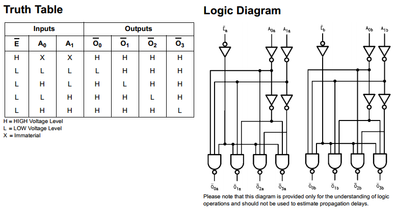
Each decoder features two selection inputs and an enable input, and has four outputs. This sounds perfect: since I only want one active signal per high/low side at a time, each of the sides gets one of the decoders and I’ll wire up two selection inputs, and the PWM will be the enable signal. This was all sounding great until I noticed that the entire chip uses active-low logic; this isn’t a big deal on the input side, since it’s easy to generate an active-low PWM, but the output is going to be fed into a MOSFET driver which seem to all have active-high inputs. This could work by putting a hex-inverter between the 74139 and the MOSFET drivers, but then we’re back up at two chips and haven’t gained much. There’s a similar 74239 chip which is apparently the same as the 74139 but with active-high outputs, but a cursory search revealed that this chip is not / no longer made.
This would let me save some pins on the ATmega, since you only need four inputs rather than the 6 with the AND scheme. Since there are only 6 commutation states, you should only really need 3 bits of selection input: by playing around with it, you can see that this is actually pretty close to possible, the only issue is that you need to AND together some of the outputs, which introduces yet more parts (though perhaps as simple as a resistor array). Saving the pins would be nice, but I decided to go with the AND method as I’ll talk about later
LED indicators
I actually found this surprisingly helpful for debugging, but I wired the 6 AND-ed control signals to six LEDs. I used serial output from the ATmega for most of my debugging, but for a quick view of whether or not things were working, the LEDs were actually quite nice.
One thing I’ve learned to do is to use the 74AC series of chips, which can drive 24mA from each output; the 74HC chips I used earlier drove LEDs too dimly.
MOSFET drivers
I didn’t really understand the need for this stage at first, but this stage is essentially a series of small transistors that the microcontroller can use to control the large power MOSFETs. Some of the resources I read said that you needed these due to high gate threshold voltages, but I found some logic-level MOSFETs that could handle the current I wanted, so I thought I could get away without it. Well, on the low-side at least; on the high-side, the ATmega328 is unable to directly control a 12V signal due to its ESD-protection diodes. I had tried using the ATmega outputs to pull the high-side MOSFET’s gates down, which worked, but when I tried to float the ATmega’s pins by setting it to an input state, the ESD diode limited the gate voltage to somewhere around 5.5V. I used a simple 2-cent NPN transistor to do this, but I was still wondering why you would want a $1+ driver.
There were a couple reasons I found:
- The driver chips can add features, though I found that the cheapest chips don’t add much that I could use for a 3-phase BLDC application.
- N-MOSFETs seem to overall be better that P-MOSFETs, in terms of both price and performance, so there’s incentive to use N-MOSFETs on both the low and the high side. This means, though, that you have to drive the high-side gate pins above the highest supply voltage in the system, which requires some dedicated circuitry
- The mosfet driver can push more current than the microcontroller, which will switch the mosfets faster, reducing switching losses.
The last point is what I think to be the most important and the one I understood the least. When I thought of switching losses, I assumed they meant the energy it takes to charge and discharge the MOSFET gate capacitance. Instead, it’s actually the fact that while you are switching the MOSFET, the gate will be at a low voltage that is intermediate between “on” and “off”, where the MOSFET allows a large current but takes a large voltage to do so, resulting in large power dissipation. In effect, either the voltage or current (depending on if you’re switching it on or off) will turn on before the other one turns off, so for an amount of time dependent on the gate current, the MOSFET is draining power.
In the breadboard picture you can see me using some “High-Low side independent” drivers, which seemed to work pretty well, though at a slightly higher price than I would have wanted.
Power MOSFETs
This is a relatively simple part of the circuit to build, but I spent an inordinate amount of time picking them out, just because there are so many darned options. I wanted to not have to heatsink the mosfets, so I was looking for some with low Rdson; when I picked out the parts I was also looking for ones that could be driven by 3.3V inputs, though for the part I picked that reduced the maximum gate voltage they were rated to handle, which I was exceeding, so I wouldn’t recommend it.
Issues
The main issue I ran into was that the ATmega kept on behaving very erratically and it took me a while to pin down all the reasons why. The main things I had to do were
- Connect ground better throughout the system. I’m not really sure how this was possible, but I was seeing 100mV swings between the two ground pins on the ATmega. I had wired up the ground on each side to the ground rails on their respective sides, but I had only connected the ground rails at the bottom of the breadboard setup. I connected the ground rails directly over the ATmega, which fixed this issue.
- I connected more filter caps everywhere.
- I had to be very careful to not connect high-voltage to the ATmega pins, especially when set to output mode. I blew out two ATmegas entirely which was actually easy to debug despite being disappointing, but the high voltage at times had more insiduous effects, causing the ATmega to skip around the program wildly and reset the timers randomly.
Sensorless control
Once I had the breadboard all set up and the electrical parts working, the main challenge was the firmware. Getting the motor to jerk around randomly was quite easy, but getting it to move smoothly, especially at high speed, was quite challenging and I’m still not done.
There are two ways to control brushless motors: you can use Hall-effect sensors to directly measure the movement of the motor, or you can measure the back-emf generated by the unused motor phase, called sensorless control. It sounds pretty daunting, but the electrical part of it is fairly straightforward: you measure the voltage on the unused phase (ie the one you’re not powering or pulling to ground), and use that as the input to your firmware.
I had a lot of issues with this because the ATmega’s ADC is either slow or inaccurate, at least in the context of this application. An ADC conversion takes 13 ADC clock cycles, and by the default the Arduino libraries will set the ADC prescaler to 128, giving an ADC conversion time of 100us. By comparison, my motor should be capable of driving at 12k rpm with no load. From some simple empirical testing, it looks like my motor requires 42 commutation steps to do a complete revolution, which means that at a full speed of 200 rotations/s, a commutation needs to happen every 120us. Clearly, a 100us ADC time makes this impossible.
I changed the ADC prescaler to 4 (setting it to 2 made the ADC not work), meaning that the ADC conversion should theoretically take about 4us. I think there was a fair bit of overhead, since I was only doing about 8 ADC measurements per commutation cycle, at significantly less than the maximum of 12k rpm. I wanted to increase the number of back-emf measurements I could do; some references suggest that you only need to do three or so, but I wanted to shoot for closer to 10 so that I could get better resolution and potentially do some debugging.
So, the method I ended up going with was using some LM358 op amps as voltage comparators, since the control algorithm only requires a threshold detector, rather than fine-grained voltage measurement over the entire range of voltages. I was pretty surprised though: this didn’t increase the controller speed at all! I think the issue was from using the Arduino’s digitalRead() function, which turns out to be quite expensive (maybe 10s of microseconds). I switched to directly reading from the corresponding PIN registers, and suddenly the system could drive the unloaded motor at 11k rpm — not quite at the max, but at this point I was maxing out the current my little wall adapter could provide. It’s quite an experience to have something on my desk rotating 180 times a second! With the propeller attached, it was able to drive the motor at about 60 rotations/s, though that was limited again by the dc adapter current. Side note — I’m planning on adapting a spare computer ATX supply I have as a simple bench supply, since it has both 12V and 5V rails and a large current capacity.
You can find the firmware here, though I would discourage using it or copying anything from it.
PCB version
The next step is to get PCBs made, which can be lighter and higher efficiency (and cooler, both thermally and socially). I made a few changes from the breadboarded version:
- I used 3-input AND gates, since you can get 4 of them in the same number of chips that I was using to get 4 2-input gates. I used the extra pin as an “ENABLE” signal, which is currently just pulled high with a 10k resistor, but it gives me the option of using it as a “hard stop” signal that bypasses the microcontroller
- I changed from using 3 “high-low” drivers to a single 3-phase driver. This should be both cheaper and more functional than my previous strategy.
- I changed MOSFETs I’m using. I went with these MOSFETs from NXP — they seemed to offer the best combination of low-cost, low-size, high-efficiency, and large number of pin-compatible options for future replacement. But again, there are so many options that it’s hard to know how good a choice this is. I picked their 2mΩ variant, which should hopefully be efficient enough to drive up to 20A without requiring crazy heatsinking.
- Added a 5W current-sensing resistor. The 5W rating seems excessive, especially since it’s a 3mΩ part, but 20A is a lot and forced me to revise my perceptions of what a “power electronics system” looks like.
Here’s the board I came up with, which measures 1.65″ x 2.15″ ($17.50 for three at OSH Park). All the components, and the majority of the routing, are on the top layer, since I wanted to keep the ground plane on the backside as pristine as possible, since I’m nervous about interference with the microcontroller, though I’m hoping that the current-sense resistor, which I put on the low side, hides some of that:

Eagle files here (same disclaimer about how you shouldn’t trust them).
You can see that I put a couple dividing silkscreen lines to visually separate the different stages: the top is the power stage (high-voltage high-current), the middle high-voltage, and the bottom low-voltage.
- Power stage: schematically very simple, but tricky to route due to the large current requirements. The large number of vias in this stage are mostly for thermal purposes, though I suppose they should also improve conductivity.
- High-voltage stage: this consists of the motor driver, analog multiplexer, and analog comparator (plus associated passives), which are all equipped to interface with the 12-18V supply.
- Digital / low-voltage stage. This stage consists mostly of the microcontroller, its parts, and the two AND chips, all of which needs to be protected from the high voltage. This stage is far more pin-dense than the other two, leading to routing congestion, which I should have foreseen before placing the ICs and starting routing, at which point I didn’t want to rip up my work.
I’ve never tried assembling something with this many components on it, especially at this density, so I’m hoping that it’s going to be assemble-able. I’m a little unhappy with the number of components I needed, particular the 5 non-microcontroller ICs on the board. I think with more careful use of the ATmega pins I could probably do away with the AND gates and the mux, but for this version I purposefully left some pins unused so that I could repurpose them on the fly if needed. I don’t think it’ll come to this, but another option is I can use a larger ATmega part with more IOs, though that costs a few more dollars.
On the topic of price, I don’t feel like I’ve hit the price target I wanted with this board — an off the shelf 20A ESC costs about $11, so I was hoping to hit around $15 per board for mine; instead, my total cost came out to about $23 for the first board. In decreasing order of amount, the main contributors are:
- $5.85 for the circuit board ($17.50 for 3). My current design doesn’t quite fit into the 5cm x 5cm seeedstudio $10 size, but assuming I can get it to fit that, this will go down to $1.
- $5.45 for 6x 2mΩ MOSFETs. Once I build the other boards I’ll get better bulk pricing ($4.90), and if I can use lower-efficiency 3.4mΩ MOSFETs (or lower), it will go down to $3.75.
-
$2.75 for the ATmega328. I have a feeling that I can use a lower-flash ATmega part, such as the ATmega88 for $2.13, or maybe I’ll bulk-order 25 ATmega328’s for all my projects, and bring the cost down to $1.75 per.
- $2.25 for 6x 3A flyback diodes. I’m not sure what can be done about this, but maybe the RMS current will be low enough that I can use smaller diodes?
- $1.85 for the mosfet driver. I think I could build a cheap replacement for this, albeit without its non-essential functionality, though the main tricky part I foresee is building the high-side driver circuitry.
- $1.08 for the 2x AND gate chips; hopefully I can get rid of these entirely.
Anyway, these are all ideas for the next round, and for now I’ll just wait for the boards to arrive and work on other projects in the meantime: it’s time to learn about switched power supplies, so I can power all this 5V circuitry from the 12V RC battery pack without a needing a massive heatsink for my linear regulator.

7 responses to “Brushless motor driver”
Excellent job Kevin, could you please post the circuit diagram and components used for those of us who would like to build your circuit.
LikeLike
Better still, you can find all the files on my github. I should mention again, though, that I don’t recommend using this design exactly since there are a number of things that I learned from it, but hopefully it can serve as a starting point for your own design! I posted a follow-up; I’ve done some more with them since that post, but I haven’t gotten around to posting more about it.
LikeLike
Great job! Thanks for sharing! I wonder if it applies to brushless motors likes these: http://www.directindustry.com/industrial-manufacturer/brushless-motor-61102.html
LikeLike
Hello Kevin,
I am also working on Sensorless BLDC motor,I am driving motor using BEMF method.
But first I drive motor in open loop without sensing BEMF. But when I go to close loop motor stuck ,and current goes to High. Can you give me some suggestion ,how to go open loop to close loop.
Thanks & Reagardsds ,
Ravindra More
LikeLike
Hi! My recollection is hazy at this point, but I had similar issues and I think it was just a matter of doing standard debugging stuff:
– getting good debug output from your project
– having it dump out the ADC values its getting and the commutation sequence that it chose.
This was easier for my design since I had the microcontroller doing the ADC, rather than having an external comparator. If you’re doing something like that, then it’s a matter of electrical debugging.
I remember that it took a lot of tuning to get it to run well. Good luck!
LikeLike
Hi Kevin, I’m working on similar project to this one but being a beginner I’m probably doing something stupid.
I’m looking for more experienced people’s advice.
Because I don’t have professional friends I just ask internet.
In this project of mine: http://www.dizzy.ai/2017/12/08/interference I have very unstable ground and power lines.
Your comments on the design be greatly appreciated if you don’t mind me asking!
LikeLike
I’m not the best person to ask, and I don’t see anything obvious. I’d try taking out the diode on the 12V line because I believe it’s not that standard. I used a small resistor in my design, though I’m not sure if that’s common or effective either.
I’m not sure about the ground issue, especially because you tried adding the extra wire and that didn’t help. Weird!
LikeLike