One of the issues I had with my last project is I had bent one of the microcontroller pins when inserting it into the breadboard, and as a result that trace was simply not being driven despite the code being correct. One debugging tool that I think would be useful to have is what I’m calling an “activity monitor”, which is a simple circuit that would show (via leds) both the logic level of the signal and whether there is “activity” on the signal, ie whether the signal is changing. I’m not sure if this will end up being useful, but it’s an interesting enough thing to design that I want to build it anyway.
My basic approach to it is to use a capacitor as a voltage-change-to-current converter. For example, if we have an uncharged capacitor and hook one end to the tested signal and the other to ground, when the signal transitions high, current will flow briefly as the capacitor fills up. If we put an appropriate resistor and led, we should be able to see this; by choosing an appropriate RC constant, we can get varied-length pulses for every transition. If we’re using an LED, though, we have the issue that the capacitor can never deplete, since that would require pushing current backwards along the LED. So, I put a diode to allow this reverse-current to pass; I could have used another LED instead of a simple diode, but I thought it would be confusing to have two separate but essentially-equal LEDs. I think it’s possible to build a rectifier circuit so that there’s only one LED, which lights up on transitions in either direction, but I thought it’d be simple enough to just show low->high transitions.
I added another LED to show the current state of the signal, in case there are no transitions happening. Now that I have two current-drawing LEDs though, I became worried about any effects this debugging circuit would have on the measured system, since I’m designing this for microcontroller-driven signals. So, I used an n-channel and p-channel MOSFET to create a simple CMOS driver to control the LEDs separately from the main signal line. My reasoning for going with CMOS over NMOS is because I wanted to make sure that the capacitor was charged/discharged quickly in both directions, though now that I think about it, it might have been possible to have this property given the simplistic nature of the circuit I’m building. Anyway, here’s the schematic for what I ended up with:

I decided to try my hand at putting this on protoboard, mostly for the hell of it, but also because I want this to be something I can actually use (eventually). This was my first attempt at using protoboard, and the main thing I learned was the importance of having a good means of holding the board in place while soldering! Here’s the top side of the board:
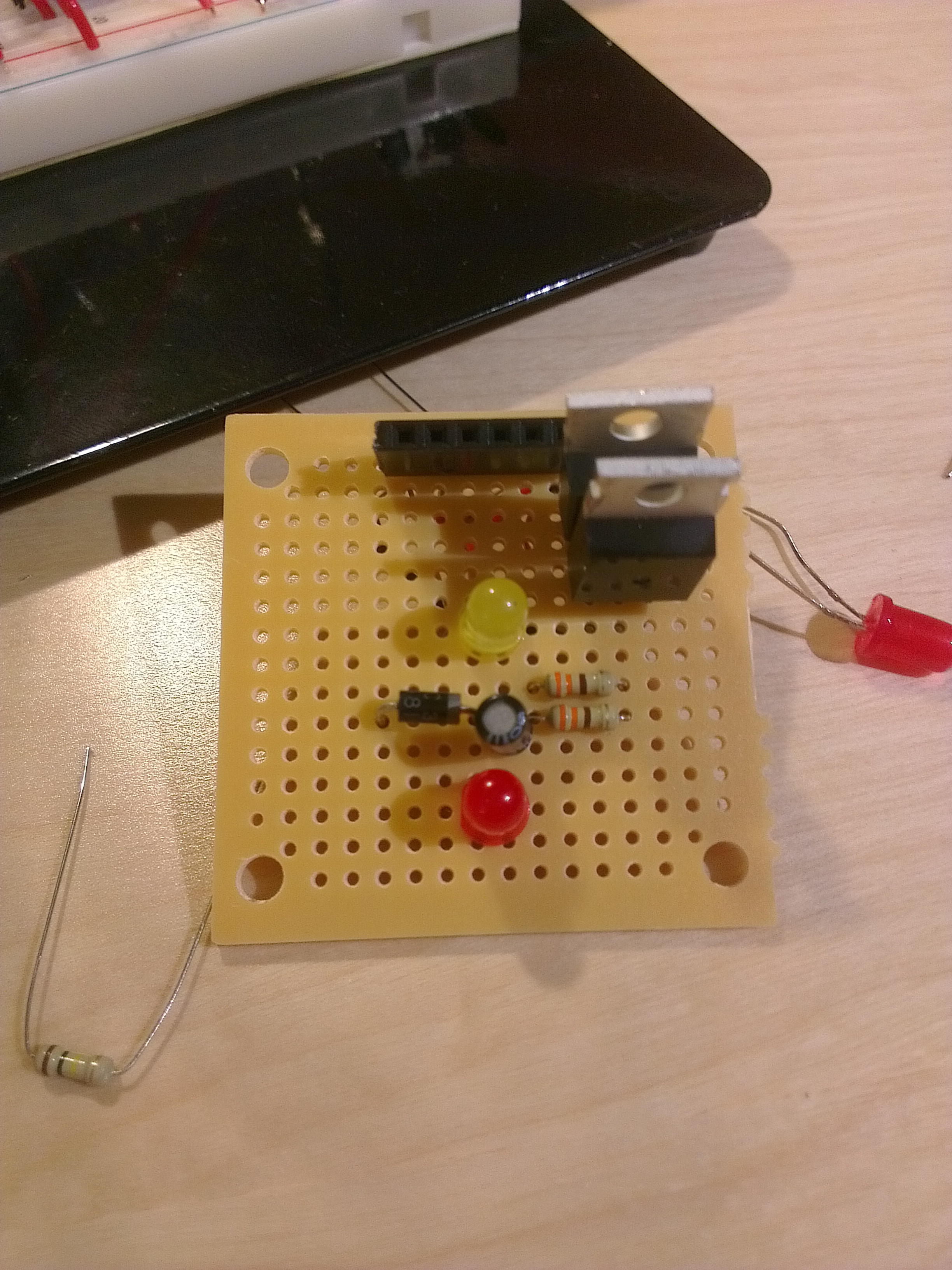
I think it looks fairly clean, if somewhat unplanned (guess why), but take a look at the bottom:

It’s hard to see since my phone can’t take in-focus photos this close, but I experimented with three different ways of connecting the components: using solder bridges (ended terribly), using hookup wire, and using the clipped leads of the components I had just soldered. The last method feels very hacky, but I was actually quite happy with the results. The wires didn’t necessarily need to come from the clipped component leads, but the fact that they were straight, thin, and uninsulated, made this a lot easier than the hookup wire.
Scaling it up
This is a simple single-bit version of the circuit, but ultimately I want to build a 4- or 6-bit version for debugging communication between my FPGA board and a microcontroller board. The MOSFETs I used are somewhat expensive, coming in at just under a dollar apiece on SparkFun, and I thought it would be a little silly to pay $8 for the components for such a simple board (my entire Shrimp microcontroller setup was cheaper!). So I started looking at Digikey to see if they have better prices, and I found some lower-power n-channel MOSFETs that came in around 30 cents each. I started looking for p-channel MOSFETs and once I put in my part criteria, saw that they have… four different parts in stock (usually there are many many pages), and the cheapest one is over a dollar.
So, I started doing some research to try to figure out why p-channel MOSFETs are so much more expensive and less common, and to determine what people do without them. Isn’t CMOS a common aspect of peoples’ designs? Don’t they use MOSFETs to implement it? I started looking around the Digikey site and saw that they sell combined p-channel and n-channel MOSFET modules, but they’re relatively expensive and have a lot of pins for all the different individual gates. Wouldn’t people want to buy a MOSFET pair that’s pre-wired in this particular configuration?
Then it hit me that there’s a very simple description of the circuit that I built, and people are probably just buying those instead of the individual transistors: I had built an inverter. And there are far better ways of procuring inverters: for example, here‘s a simple 6-element inverter that costs a grand total of $0.33, the price of just one of the n-channel MOSFETs I was thinking of buying. What’s the catch? There might be something else I’m missing, but the most obvious thing I’m seeing is that this particular inverter is only rated to source or sink 4mA of current, compared to the SparkFun MOSFET which (with a heatsink) is rated for up to 30A! I ran a quick test, and it looks like 4mA is enough current to adequately drive LEDs, so it looks like this should be a pretty reasonable option for this particular use. There are also buffer options that cost about twice as much, and there are “buffer amplifier” options that cost about ten times as much but are rated to drive much more current; I bought a couple buffer chips just to play with, but my plan is to use the inverters.
The only catch is that it’s on Digikey, and it pains me to think about paying $3 to ship a $0.33 part, even if I buy two of them for redundancy. SparkFun, where I’m trying to order from since I’m getting some of their other stuff and I like them, unfortunately doesn’t have any buffers or inverters, though they do have a much more sophisticated optoisolator. So, I spent some time browsing Digikey (they have a ridiculous amount of stuff), and ended up getting some other things like the ATmega328’s larger brother, the ATmega1284. SparkFun actually has quite good prices for many items, though it seems like one area that they don’t is with capacitors, so I bought a bunch from Digikey for about 1/3 the SparkFun price.
So now, while I wait for the stuff to arrive, I’m learning for about Eagle, with the goal of producing a simple 4-bit PCB version of this circuit.
