This is a followup to some of my earlier posts, where I take the design from this post, have it made by OSH Park as in this post, and finally now I talk about what I needed to do to fix it up and get it working.
Getting it working
Creating a custom circuit board is pretty far out of my comfort zone, so going into this project I was pretty worried that I’d produce a broken or useless circuit board. I think I spent most of my time worrying about mistakes like connecting supply to ground or picking an under-voltage part that would catch fire once I plugged the circuit in. Luckily, the issues were much more mundane, and I was able to produce a working board on my first ever attempt, which I think is a testament to the systematic-ness of the process, as well as the simplicity of the design I decided to make.
Dim LEDs
As I mentioned previously, the biggest issue I noticed is that the LEDs were quite dim. I had worried about this when designing the circuit, since I went with an inverter part that can only drive about 5mA of current; since I wanted it to drive two LEDs, I limited each LED to about 2mA, well below their 20mA rating. I tested whether this would work by running one of my LEDs at 1mA, and I found the brightness to be acceptable, so I went with the low-current inverter. Unfortunately, I had tested with a 5mm LED instead of the 3mm ones I had swapped into the design, so my thought was that the 3mm LEDs must just have a lower brightness-per-mA rating than the 5mm ones. I thought of two options: pick a different inverter part, or different LEDs. I ended up ordering both, to have both options open for testing.
After doing some searching, I picked this new inverter, which offers 24mA current per output. Now I just had to replace the inverter, as well as the LEDs’ resistors; I was definitely appreciating that I had only soldered one out of the four lanes. I’ve been pretty unsuccessful in the past with removing parts from a board using desoldering braid, so I had bought myself a $5 solder sucker and this was my first big chance to use it. I have to say, once I figured out the technique to it, it worked amazingly well — the trick was to put the soldering iron on the top of the board and the solder sucker on the bottom, so that the pump could create an almost-complete seal against the board, and almost fully clean out the hole. There was some residue left, which I cleaned up with the desoldering braid, and after some finnicking they all eventually came out.
The result, though, was quite disappointing: the LED was still quite dim! To isolate whether or not it was the LED or the driver, using some alligator clips I manually hooked 5V to before the resistor; in retrospect this was probably pretty dangerous since it could have blown out the inverter. Luckily, it didn’t, and since the LED was still dim, I tested another LED, saw that it was bright, and replaced the ones on the board. After doing that, everything worked fine, so I soldered in the other three lanes, put on some standoffs, and had my first board!

Stray capacitance
I spent a fair amount of time just playing with the board, since I found the behavior to be quite interesting when I didn’t connect the inputs to anything. The first thing I found is that the state that the inverter reads / pulls the inputs to when they’re floating is a logical ‘0’; the interesting thing is what happens when I briefly connect an input to Vcc, then disconnect it:
The logic level goes high while connected, then reliably stays high for a second or two, then goes low again. My interpretation of this is that there must be “stray capacitance” that affects these input pins, so I’m effectively charging a very small capacitor when I connect it to 5V, and it takes the inverter a few seconds to discharge this stored charge. I was curious how much this capacitance is — but once I started thinking about it, I wasn’t sure if I would be able to actually measure the capacitance, first because the value is so small, and second because it probably depends on the input being connected to the inverter, so it’s not clear if I can isolate it.
What I did was I connected an additional discrete capacitor between the input pin and ground, to see how much longer the “high” logic level persists. I didn’t bother using a stopwatch since I was just curious about the rough magnitude, but adding a 10pF capacitor (the smallest I have) seemed to increase the delay from about 2s to about 5s, so I’m going to say that the stray capacitance is on the order of a few pF. I just checked the inverter’s datasheet, which lists a typical input capacitance of 4.5pF; I’m not sure if this is the same capacitance as I’m measuring, but it seems to make sense both logically and since the capacitance values line up.
Touch sensitivity
The next thing that surprised me is that when left disconnected, the input pins are actually sensitive enough that they can detect when I touch them with my finger!
I guess that with a 5pF capacitance, the slightest voltage fluctuation is enough to cause the inverter to switch states. I thought it was pretty cool that it’s so easy to create a touch-sensitive device that you can do it accidentally, but I’m not sure that this particular effect is practical, since there were many other (less-interesting) thing I did that also triggered the circuit, such as bending the power supply leads.
Seeedstudio Fusion boards
Shortly after I had sent out the PCB order to OSH Park, which is where the boards in the above photos+videos are from, I submitted a slightly-modified design to Seeedstudio. I found their 10-boards-for-$10 option to be quite appealing, and I wanted to test it out and compare the resulting boards. The only problem was that the $10 option has a 5cm x 5cm limit, and my original board was slightly too large (42mm x 65mm). It’s possible that I could have shrunk the board my being more aggressive about placing components next to each other, but I thought that this would be a good opportunity to experiment with surface-mount components, since I this order was already experimental in nature.
Seeedstudio fabricated the boards much more quickly than OSH park (a few days vs over a week), but since they’re based in China, the shipping was much slower, and the overall turnaround time ended up being 3 weeks vs 2 weeks for OSH Park. Here’s a picture of what I got back:
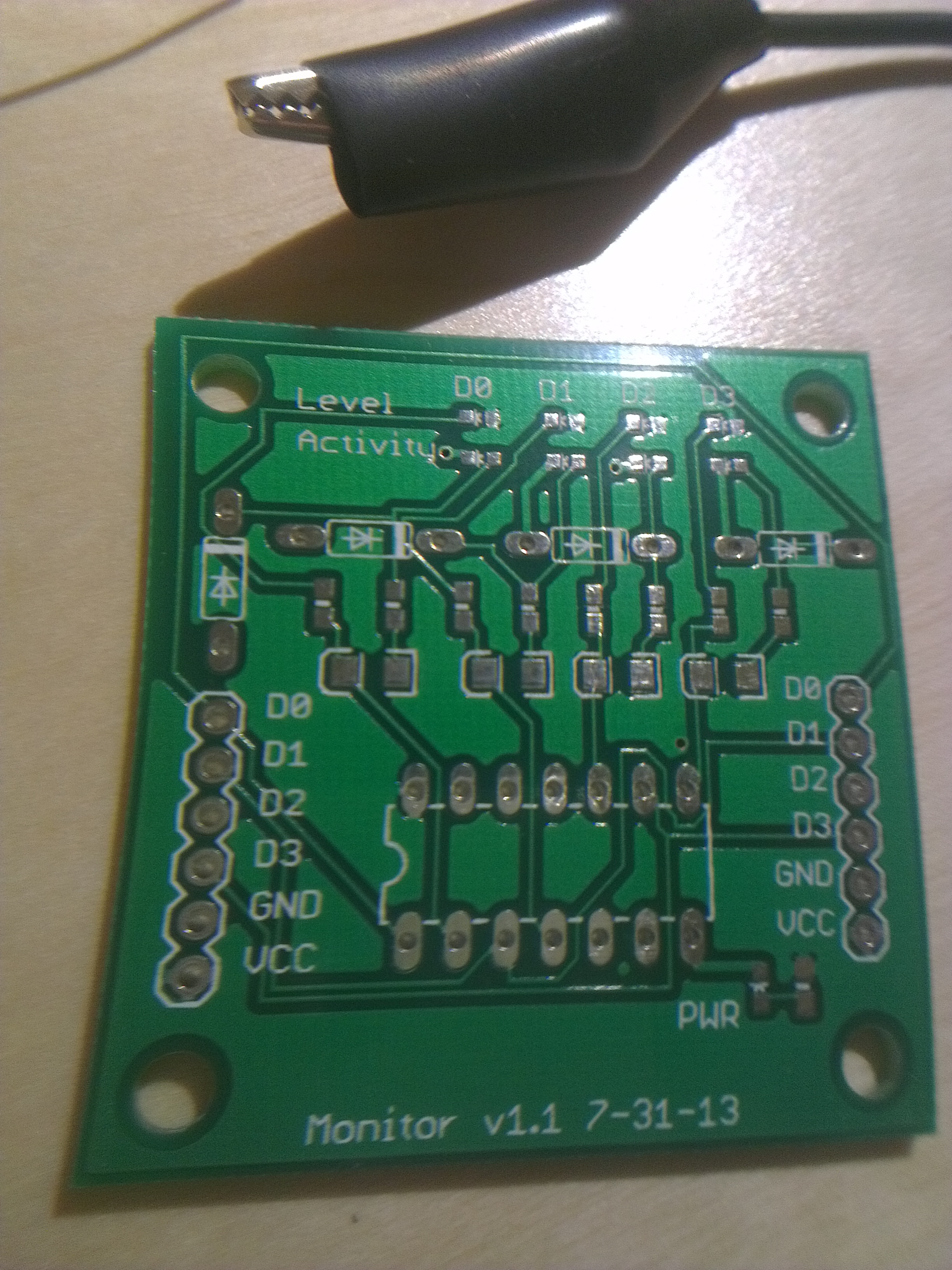
You can see that I’ve very-professionally labeled the board with the revision number and date 😛 I didn’t examine the boards too closely, but they overall seem well-made, though I didn’t go anywhere close to their specified minimum tolerances. I’m not super happy with some of the silkscreen; in particular I found it very hard to tell which way I should put the LEDs. To be fair, I had this same exact issue with the OSH Park boards, despite the LEDs there being much larger, so I think it might be an issue with the Eagle parts I’m using; it should be a good test to modify the silkscreen on them.
It was pretty cool to see all the surface-mount (smd) pads on my own board, and since I’ve been doing a bunch of reading about soldering smd components, I felt fairly good about my prospects.
Starting the job
I immediately ran into some issues assembling this board: first, I tried to show my girlfriend just how small a 0603 component is, and in the process I lost the first of many resistors. The second is that smd components have a completely different set of markings on them; this is ok for the resistors, since I’m keeping them in their labeled bags, but was a hurdle for the leds and capacitors since I wasn’t sure how to read the polarity on them. I started the assembly by soldering the power LED and its resistor; doing an electrical test made everything look in the clear, but I connected the power and the LED didn’t turn on. Using my multimeter again, I discovered that I had placed the LED backwards, and also that the “diode” mode on my multimeter will actually drive enough current to light the LED dimly.
So, I removed the LED and tried to put it on in the other direction. I was having a lot more trouble putting it on the second time, which I had expected, but eventually I had to just give up. I took a closer look, and I had actually ripped off one of the pads without even noticing it! Thankfully the LED and its resistor are right next to each other, so I simply created a solder bridge between the two, which solved the problem.
Rest of the assembly
Thankfully, this board only uses a small number of different types+values of components, so the soldering was pretty straightforward, if a little painstaking. Unfortunately, I had placed the capacitors backwards — I dislike that the stripe is on the positive side, rather than the negative side like electrolytic capacitors. So I had to remove+resolder four capacitors. I’d already done this once, so it wasn’t completely new to me, so I went ahead and started doing it… and immediately ripped off the pad from one of the capacitors. I realized that I ripped it off because the capacitor was still soldered to the pad when I tried to remove it; from removing through-hole components, I’m used to having to tug a fair bit to get the component out, but this was definitely the wrong way to think about the surface-mount ones. Once I realized this I had better success with the last three capacitors, only ripping off one of the pads, and only barely. Here’s a close-up of some of my touch-up work:

I connected it all up, and thankfully it all works, except for the fact that I ran out of diodes. Here’s a comparison of the sizes of the two boards; I’m pretty happy with the size reduction, but I think that I can be much more aggressive about packing the components together.

Thoughts on surface-mount soldering
This board definitely tested my soldering skills — incidentally, people actually do sell soldering practice kits, but my version costed less and is actually useful at the end. I only used 1206 capacitors, which I found to be quite easy to handle (though I had to get used to removing them), and 0603 resistors+LEDs, which definitely were tough but I felt like it was only about as tough as I felt my first few through-hole boards were at the time. I can definitely imagine it’s possible to get to the point that I feel comfortable soldering 0603 components, which is good because I have a board coming in soon that uses 0402 capacitors.
It definitely took me a lot longer to assemble the surface-mount version of this board than the through-hole one, but I think that that’s largely a function of it being my first time doing surface-mount soldering; given the cost savings, both from the components but more significantly from the reduced PCB costs, I can see myself making all my boards surface-mount from now on.
