One issue I’ve quickly run into is that I want to embark on new projects, but don’t want to completely disassemble my existing projects in order to get the parts I need. For some parts of the project, like resistors and wire, it’s pretty easy to over-buy those and not need to scavenge old projects for them. For other things like breadboards, it’s less easy, but at $5 a breadboard, I don’t mind over-buying these as well.
The most expensive common component I have, though, is the Arduino-like microcontroller board that I use as the project base. A real Arduino will run you about $22 on Amazon; there may be cheaper options out there, especially if you’re willing to buy older versions, but this is the cheapest retail one I’ve seen so far (usually they’re about $30). These things are highly versatile and I wouldn’t mind having a couple extras of them, but they’re expensive enough that I’m not quite ok saying that I’m going to buy one per project I’m working on.
One very simple option is to simply disconnect the wires from the Arduino when I want to move it to another project, and reconnect the wires when I want to get a project running again. I actually did this for a while, but this quickly became unmanageable, since I was having to remember exactly where all the different wires go.
Another option I’ve tried is to use the shield interface as a glorified connector, so that reconnecting the Arduino is just a matter of reattaching the shield:
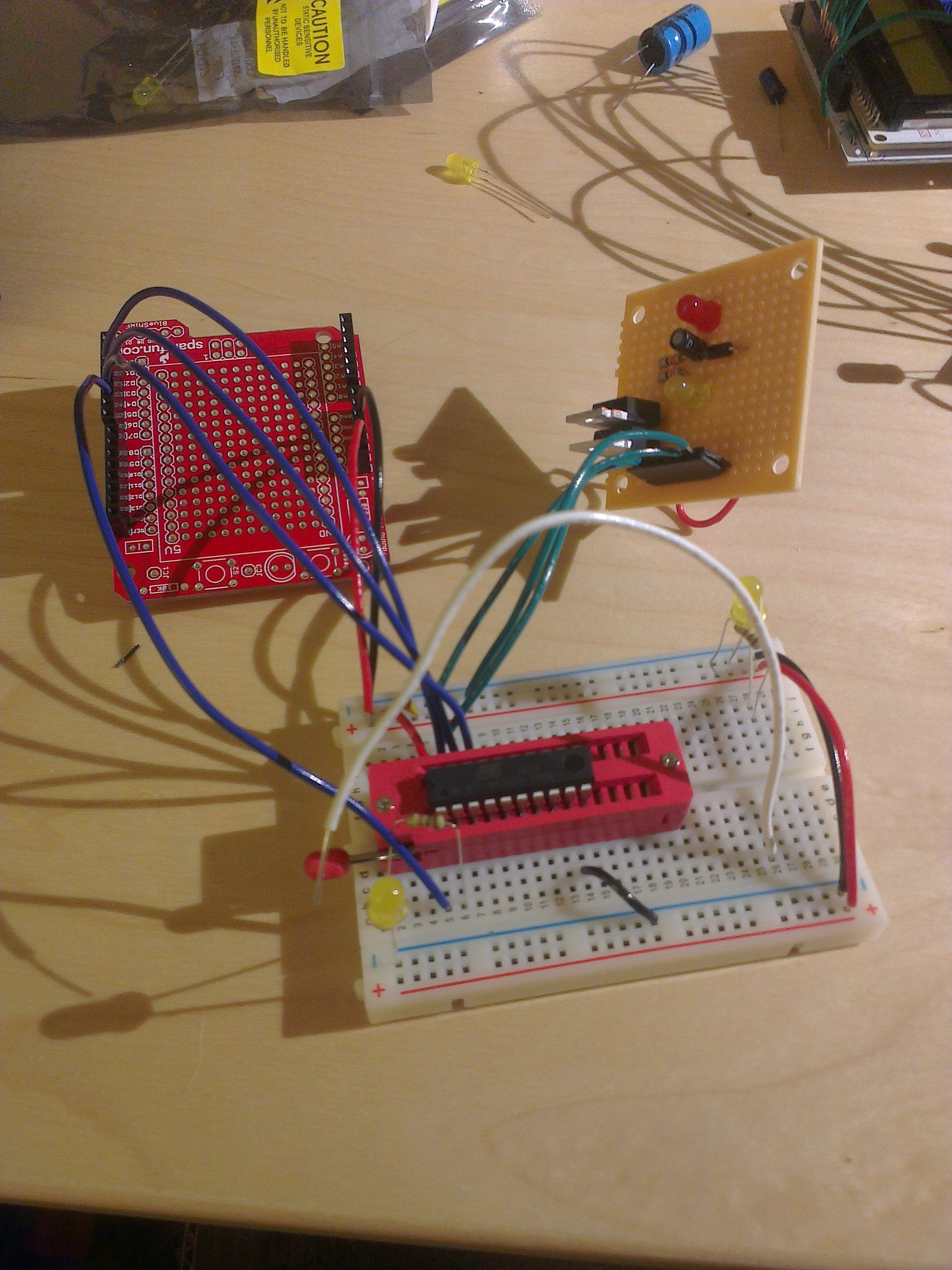
I’m using the SparkFun ProtoShield PCB ($5) with a set of Arduino stackable headers ($1.50), to give me a “connector” which is easy to snap onto Arduinos. This system has served me fairly well, but at $6.50 a shield, I feel like I don’t deserve to be swapping these out all the time.
So going back to my original thought, it’d be nice to be able to leave a microcontroller board connected to each project, but to not have it cost $22. I looked around for some lower-cost Arduino variants, but pretty quickly I decided to build my own instead.
Enter the Myduino
Fortunately, with the popularity of the Arduino, there are many published schematics for Arduino-like microcontroller boards. I’ve built my existing boards off of The Shrimp schematics, so I used that again as a base for this new board. There are a couple ways I had to modify it, though, for its new purpose: first, I need an interface for connecting from the computer to the board in order to program it. I decided to use the SparkFun “FTDI Connector“; I’m not sure how much of a standard this is, but they have it in their Eagle library and it has exactly the pins I wanted, so I decided to go with it (plus I can buy that cable if I want to).
The second decision is how I want to connect from the board to the rest of the project. I decided to stick with the theme of using female headers, but instead of having four separate headers, I decided to have a single 2-row header, to reduce space.
The last decision is what to call it. I’ve never felt great at naming things, so I decided to not put too much effort into it and just call it the Myduino 😛
Here’s the schematic I came up with:

There’s not a whole lot going on here that isn’t common to all ATmega328-based boards, so I’m hoping I didn’t mess it up. One thing I’ve realized in the course of writing this blog post is that I forgot to bring out GND and VCC to the header on the right, so I’m thinking I’ll solder some extra loose wires to some of the exposed pads.
The thing that’s probably more interesting is the board layout. As I mentioned, one of the primary drivers for this project is to create a low-cost alternative, so my primary goal for the board design was to reduce the board size, since the board cost is directly proportional to its size. So, the board is quite small (1.7″x1.35″ to be exact); you can get a sense of proportions by noticing that that’s a 28-DIP ATmega328 in the middle. Here’s what I came up with:

Note — all the grey writing (not the white) is stuff that doesn’t appear in the final board construction; I probably should have turned it off entirely. Also, there is a ground plane on the back (blue) side, but I usually turn that off for visualization to keep things cleaner.
This board is quite a bit more aggressive in its design than my first board, in a couple different ways. First of all, I used surface-mount components (only simple two-terminal ones), which I’ve never used before. Second, I actually put some of those components on the bottom of the board to explore the limits of doing that: I feel like I probably can put whatever components I want on either side, including through-hole ones, but I wanted to start first with just the decoupling capacitors, which are generally held to be easy to put on the bottom.
Third, I reduced the pad sizes on the header on the bottom. The header has a pin spacing of 0.1″, and the SparkFun library where I got this from has the pads have a 0.075″ diameter, giving a 25-mil spacing between the pads. I very much wanted to route the traces between the pads, but I also want to be using 10-mil traces with 10-mil spacing, which won’t fit. I had two options: decreasing to 8-mil traces with 8-mil spacing, or decreasing the size of the pads. Decreasing the trace size probably was the “right” choice, since OSH Park can do 6-mil traces with 6-mil spacing, but I’m feeling confident in my soldering and I wanted to test pad-size limits too.
Fourth, I used a ground plane, since that seems like a good thing to do.
Lastly, I did all the routing on this board by hand. Part of the reason for why is because when I first tried auto-routing it, I used the wrong settings (50-mil grid width) which made the autorouter totally unable to route the board. In retrospect, though, I’m pretty happy that I did the routing manually, even though I re-ran the autorouter with better settings and it was able to do it.
I submitted the order to OSH Park for a total cost of $11.45, and I should be getting it back in a few weeks. There are a couple changes that I’m thinking about making, but I’m trying to hold off until I get the boards back to submit a new rev.
Cost
So, did I succeed in making this cheap enough? Here’s the bill of materials; except where noted, all prices are from DigiKey and don’t include any bulk discounts:
- PCB: $3.82 from OSH Park ($11.45 for three boards)
- ATmega328-PU: $2.88
- 1x 20-pin female header: $1.35
- or 1x 24-pin female header: $1.73
- 1x 6-pin female header: $0.67
- 1x 16MHz crystal: $0.36
- 1x pushbutton [couldn’t find this exact one on DigiKey and it’s cheaper on sparkfun]: $0.35
- 1x 10uF capacitor: $0.18
- 2x 22pF capacitor: $0.10 each
- 2x 10nF capacitor: $0.10 each
- 1x 100nF capacitor: $0.10
- 2x SMD LEDs: $0.08 each
- 2x 330 ohm resistors: $0.02 each
- 1x 10k ohm resistor: $0.02
Which comes out to $10.33, not including DigiKey shipping (starts around $3). I’m actually pretty surprised by this; I thought it would be cheaper, since the board is so minimal. I guess I didn’t expect the headers to be so expensive. I can think of a number of ways to cut costs if I wanted to:
- Use seeedstudio to bring the PCB cost down to $1.52 ($9.90 + $5.30 shipping, for 10 boards), though I haven’t received my test boards from them yet.
- Use a cheaper ATmega part, for instance this one looks pin-compatible and is $0.80 cheaper
- Redesign the board to not bring all 20 pins out separately to the header. I rarely use more than 8 of the pins on the Arduino, so one possibility is to have a 10-pin header with two of the ATmega pins connected to each header pin, letting you drive the header from either pin.
- Use male headers instead of female ones. This might actually make a lot of sense for breadboarded projects, since the male header could be inserted directly into the breadboard.
- Buy in bulk; this is particularly true of the $0.10 capacitors, which decrease in cost to $0.024 if you buy at least 10 of them.
Overall, right now I’m not dying to implement any of these (except maybe the buying-in-bulk part), since this is cost competitive with the $6.50 “shield connector” option, and will hopefully be way easier to use. Now I just have to wait for the boards to arrive, and figure out a plan for the meantime since I still have projects I want to do.

One response to “Myduino: creating a low-cost arduino substitute”
Thanks for the pingback, Kevin
Thought it would be worth sharing our experiences trying to get the cheapest possible project board. The @ShrimpingIt work was inspired by a very similar problem statement.
We’ve hit a price point around UK £2.15 ($3.32) which looks like this… https://www.facebook.com/photo.php?fbid=118928131599823&set=a.118928128266490.23156.118100035015966&type=3&theater based on using £0.15 of stripboard, and mirroring our standard breadboard layout. Not as small a layout, though and I can see you’ve had a lot of fun designing yours too.
It leads to two male breakout strips (one either side) which are pin-identical to the ATMEGA pinmapping. You can produce nice ‘shields’, though each side is separate when using this approach. It seems a decent compromise for hacking, though. Headers we source from…
http://www.taydaelectronics.com/40-pin-2-54-mm-angle-single-row-pin-header.html
http://www.taydaelectronics.com/40-pin-2-54-mm-single-row-female-pin-header.html
…alongside the other electronic components for the circuit – Tayda basically sell everything except the UART. These headers can solder at the edge of the stripboard on each module so they dock together.
If you can afford to wait for parts, the suppliers listed from our recipe page at http://shrimping.it/blog/bill-of-materials/ are pretty much international, and as cheap as you can get, though maybe you’d need to be buying 10 or more to get anywhere in the ballpark of our bulk prices.
Even getting bagged supplies from us direct (at twice wholesale) would be around the £4.50 ($6.95) mark, based on cutting our stripboards into 3, being…
http://shrimping.it/blog/shrimp-kit/
http://shrimping.it/blog/stripboard-kit/
…but this doesn’t cost in if you’re a hackspace or classroom wanting 100 kits and with plenty of time on your hands – if that applies to you, you can follow through our kit information to source supplies direct for half our prices.
Also worth considering the CP2102 as a very cost-effective alternative to the FTDI
http://shrimping.it/blog/cp2102-kit/
…and interestingly BAITE now has responded to our request to ship a CP2104 with pre-soldered DTR breakout…
…and their CP2102s will follow suit very soon!
LikeLike