I have a pretty simple-sounding circuit I want to build, but am surprisingly having quite a bit of difficulty finding any guidance about it on the internet (maybe I haven’t found the right google term?). It’s this: I want to provide a battery backup to a system, so that it can seamlessly switch between being plugged in and not. When plugged in, though, the battery should recharge. This is how any portable consumer device works, but surprisingly not how people seem to use batteries in the DIY space. So the question is, how exactly do you make the system switch between the battery and the charging-source?
The simplest, most straightforward way is to set up your charging circuit and then connect the load directly across the battery, like this:
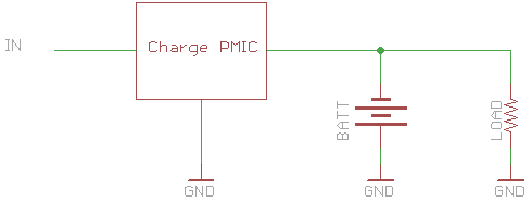
When running on battery power, the battery will just feed the load; and when plugged in, the charger circuit should split its power between the load and recharging the battery. And if the load draws more than the recharger can provide, the battery should make up the difference. Maybe you should add a diode so that the battery voltage doesn’t back-flow into the charger IC, but you get the idea.
But the question is, is this safe? It seems to me like it should be, but with lithium batteries I don’t want to take anything for granted. Surprisingly, I haven’t found any sources online saying whether it is or isn’t. There are plenty of people who offer complicated schematics, and I can come up with explanations for why they might be better, but I haven’t seen any explanations of why the easier option isn’t sufficient. One reason the complicated options are better is, for example, is if you connect the input voltage directly across the load (and use a transistor to control whether the battery is connected to the load), this lets you use the full capacity of the charger for the battery, while still powering the load (in the simpler design, the charge current is split between the battery and the load, increasing charge times). This doesn’t seem like a huge drawback for my use case, though, since recharging time isn’t the most critical.
Maybe there is some issue that the charger will preferentially charge the battery instead of powering the load, though my feeling is that since the frontend of the load will be a voltage regulator, the regulator will try to make that not happen; in other words, the regulator should provide a much lower-impedance path than the battery (assuming the load is under-powered) which will take the vast majority of the current.
Anyway, if anyone knows more about whether this is done or not, please let me know, since I’m about to build a circuit like this!
Update: well, I don’t really have any more answers, but one thing I think I’ve decided for myself is that I want to build an undervoltage-lockout circuit, which shuts off the power from the battery when the voltage gets too low. This is for the safety of the battery, since it will over-discharge itself, which is bad for the battery, and who knows it’s probably unsafe too. Since I’m planning on having circuitry to disconnect the battery from the load in this situation, it seems like it won’t be too difficult to update the “turn off” condition to also include “or if the USB adapter is plugged in”.
Update #2 (4/12/14): actually it looks like maybe the approach in this post — directly connecting the battery and load — may be appropriate, though I’m not sure how under-voltage lockout is supposed to work. I’m leaning this way since I just saw that SparkFun released a battery charger board that works exactly like this — you can see here in the schematics that the battery and load are directly connected, and this is also what’s suggested in the datasheet for the charger that they’re using. I’m not any closer to actually having a need for having battery backup for my project, but it’s still cool to think about.
